GPUs
GPUs
Popular models
Popular models

| Name | Vega 10 |
| Foundry | GlobalFoundries |
| Process Node | 14 nm |
| Transistors | 12500 million |
| Die Size | 495.0 mm² |
| Density | 25.3 /mm² |
| Cores | 3584 |
| TMUs | 224 |
| ROPs | 64 |
| Technology | HBM2 |
| Size | 8 GB |
| Bus | 2048 bit |
| Bandwidth | 409.6 GB/s |
| Speed | 1.6 Gbps |
| Base clock | 1156 MHz |
| Boost clock | 1471 MHz |
| Memory clock | 800 MHz |
| 8-pin | 2 |
| TDP | 210 w |
| Recommended PSU | 650 w 550 w |
| DisplayPort | 3 1.4a |
| HDMI | 1 2.0b |
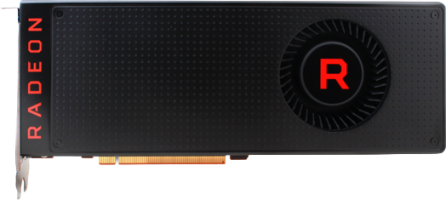
| Slots | 2 |
| Length | 269 mm |
| Height | 112 mm |
| Width | 40 mm |
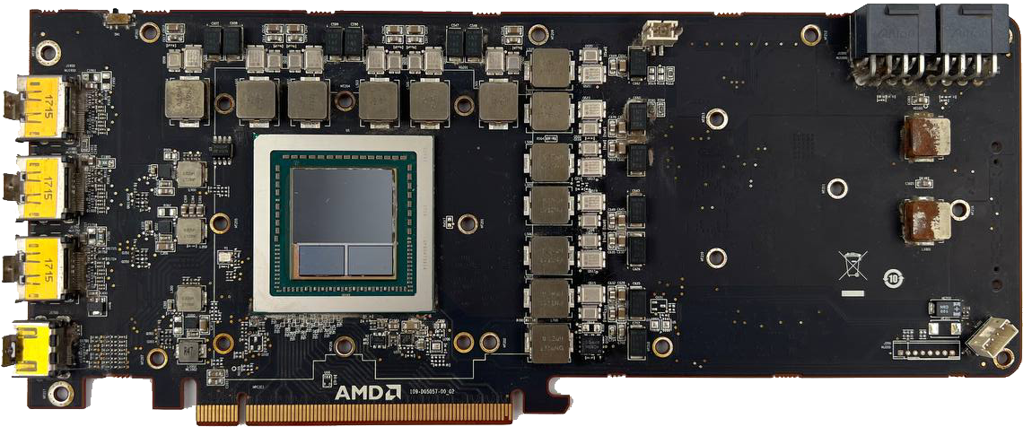
6 screws holding the backplate in place
2 screws on the top of the I/O shield holding the cooler
10 screws around the back of the PCB
4 screws, one is hidden under the warranty sticker
Lift with a spudger, don't pull the wire.
Lift with a spudger, don't pull the wire.
Gently break it loose from the thermal paste/pads
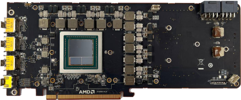
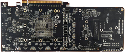
| GPUs▲ | Price▲ | Boost clock▲ | Slots▲ | Length▲ | Height▲ | Width▲ |
|---|---|---|---|---|---|---|
| 1471 MHz | 2 | 269 mm | 112 mm | 40 mm |
 Price alerts Write review